How to Install The AK Fire Control Group
Travis Olander 03.20.23

Whether chasing tighter groups or trying to keep your foreign-made Kaleshnikov 922r-compliant, a hammer and trigger upgrade might be on the books. This guide covers how to swap the AK fire control group, or FCG. The FCG comprises the hammer, trigger, sear, disconnector, and safety. We’re using a stripped down Molot VEPR chambered in 7.62x54R for this guide. Let’s install an AK Fire Control Group.
Although it uses an RPK receiver, the VEPR is no different than the AK-47 in form and function. These install steps apply to any milled or stamped steel AK or RPK with the usual two-pin FCG. Most rifles fall under this category. You’ll only need a few tools and about 15 to 30 minutes get the job done:
Tools Required or Recommended
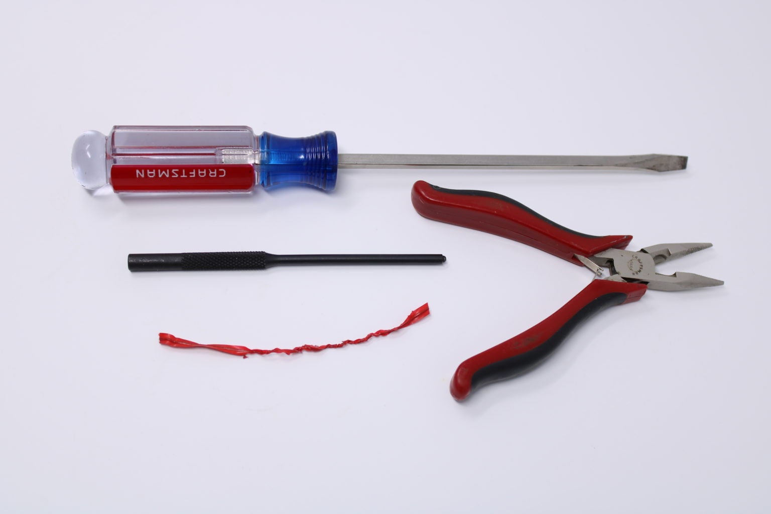
- Flathead Screwdriver: A flathead may be required for removing the dust cover and for squeezing the main spring into place.
- Small Punch: If the hammer and trigger pins are tight, a small punch will help dislodge them from the receiver.
- Pliers: You’ll need pliers to pick, move, and safely bend the ends of the main spring out of the way.
- Bread Tie: Grab a loaf and take the wire bread tie. You’ll want it to temporarily tie up the main spring’s ends.
The Hammer, Trigger, and Disconnector
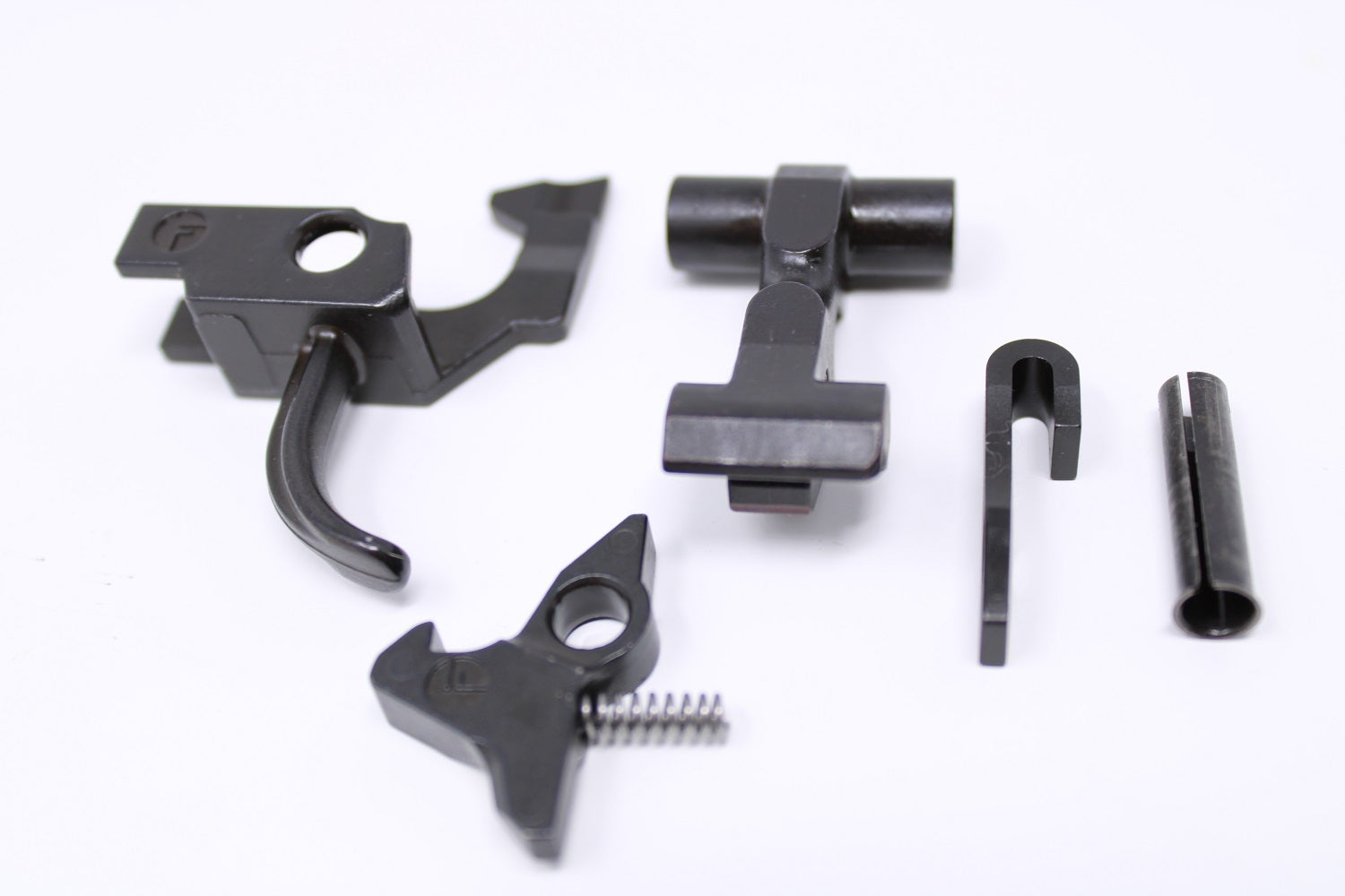
For this install, we’re swapping out our VEPR’s factory hammer, trigger, and disconnector for a US-made trigger group offered by the FIME Group. We’re doing this to ensure our imported rifle remains compliant under 18 USC 922 Regulations, which require that any foreign-made weapon not suitable for sporting purposes contains no more than 10 foreign-made parts in its construction. This is why our rifle also has no handguard, buttstock, or pistol grip. If you’re performing such an install for this same reason, know that this trigger group swap counts as 3 US-made components under 922R.
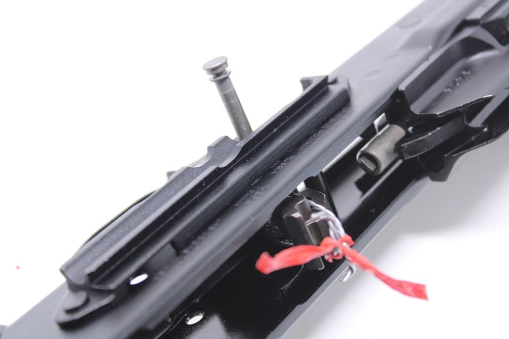
Step 1: Remove Dust Cover
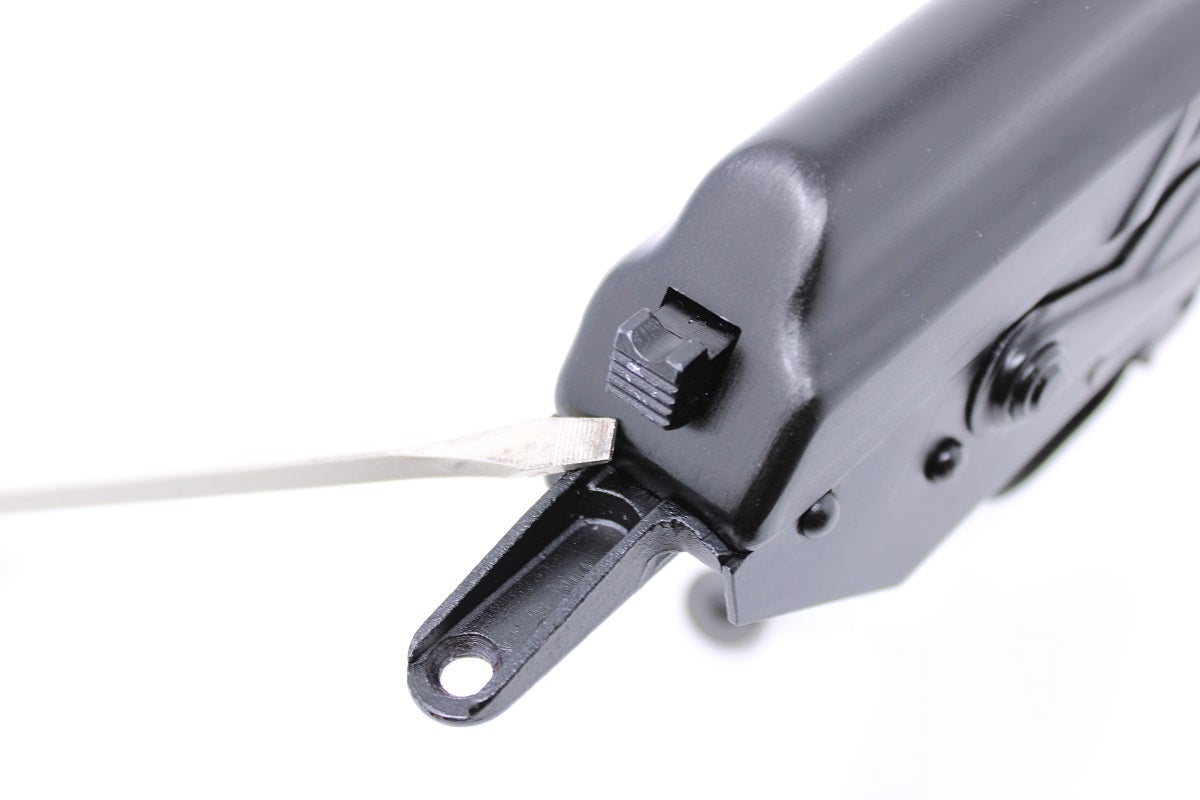
Remove the dust cover to expose the recoil spring and guide rod. A flathead screwdriver is useful for depressing the recoil spring rod’s button head, which keeps the dust cover in place.
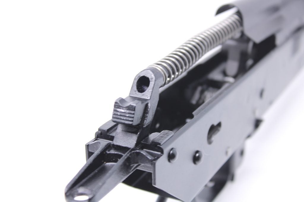
Step 2: Remove Recoil Spring & guide Rod
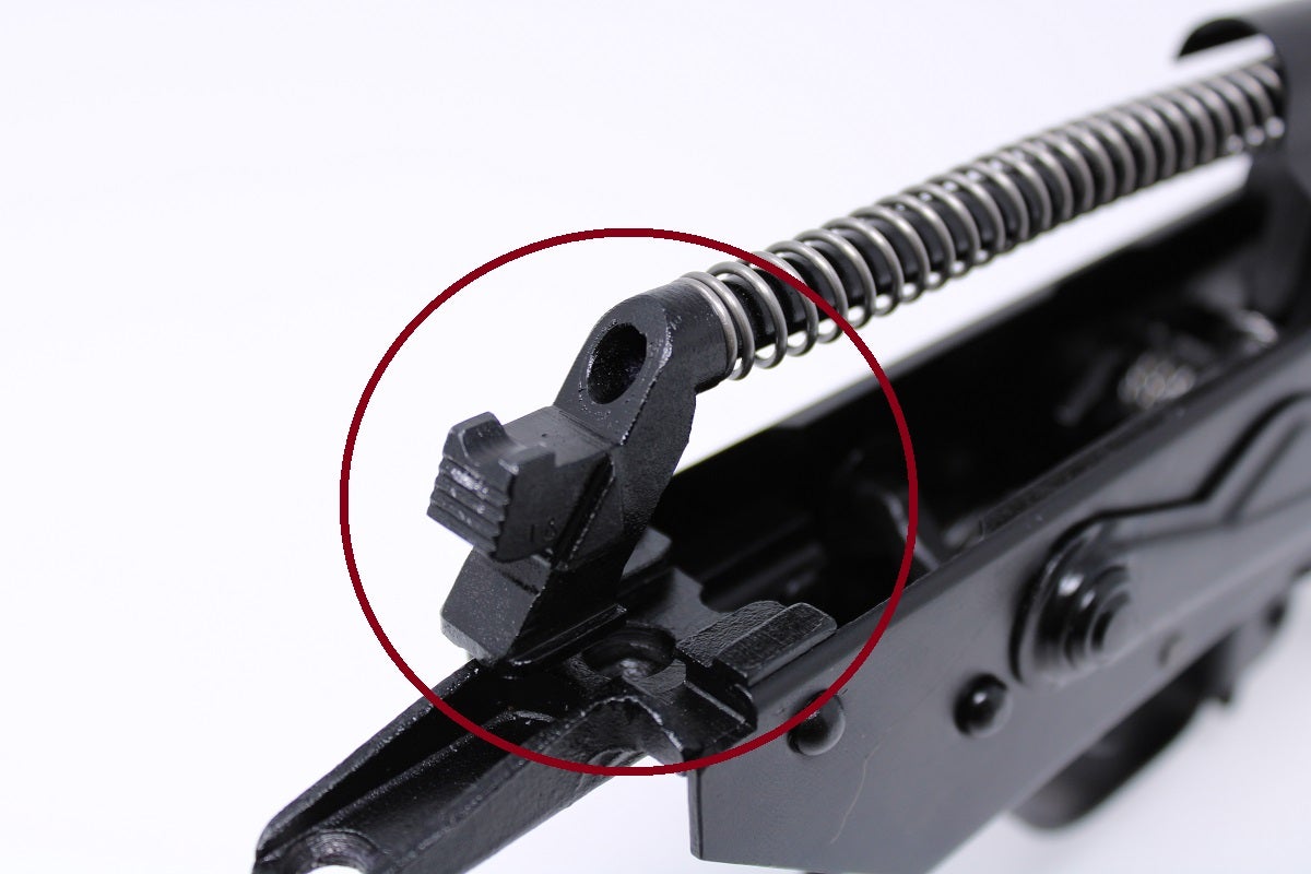
To remove the recoil spring and guide rod, press the button head of the rod forward, toward the barrel, until the bottom of the rod slips out from its seated position in the receiver. Then pull the guide rod and spring out from the bolt carrier.
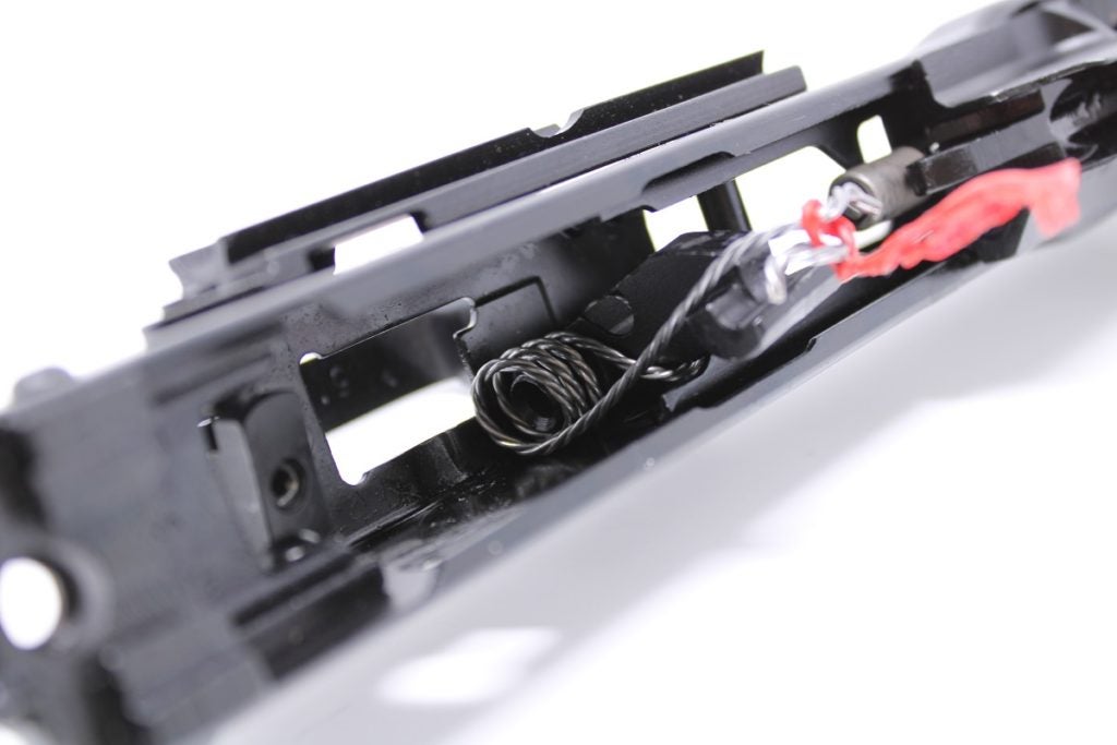
Step 3: Tie Main Spring Ends to Hammer
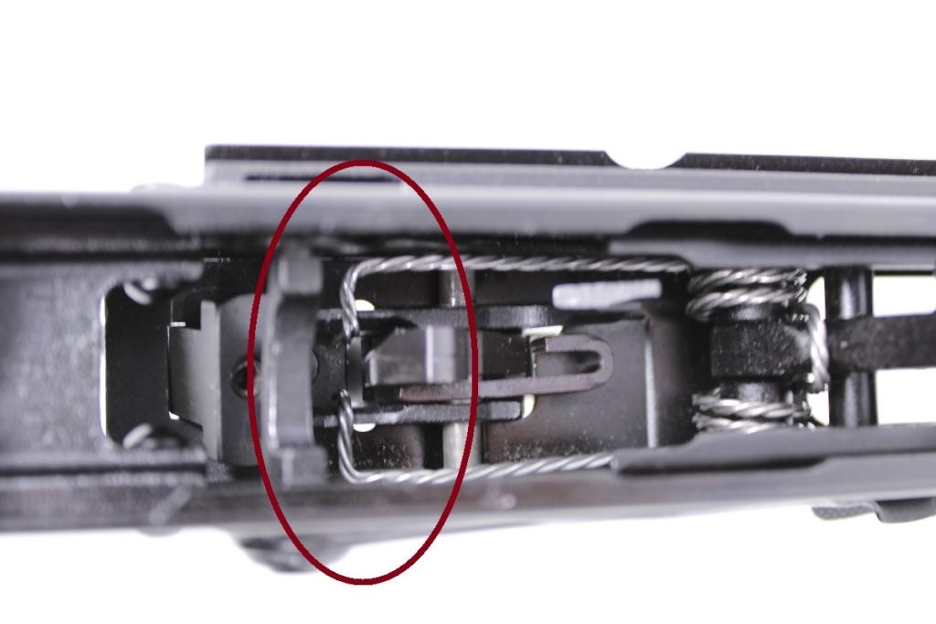
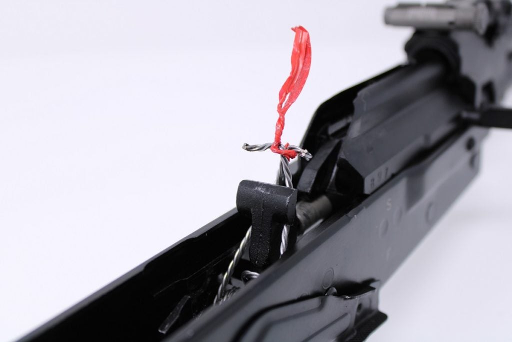
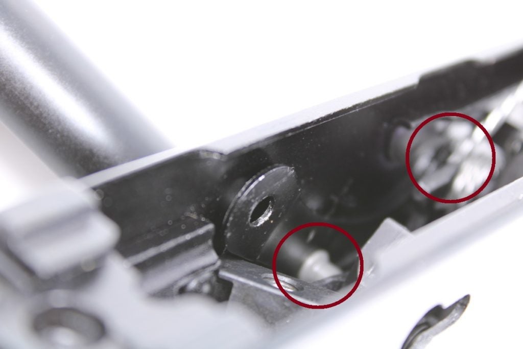
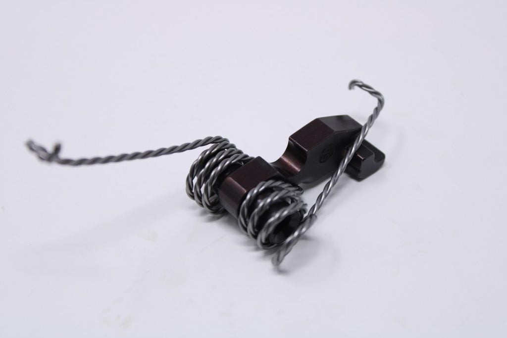
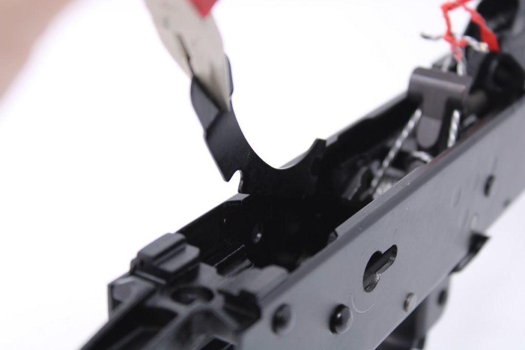
Before we begin disassembly, we need to remove the main spring ends from atop the trigger, and tie them around the hammer face. You’ll need pliers to do this. Grab one end of the spring and grasp it firmly. The spring is under a high amount of tension and that tension will increase as we work. Navigate the end of the spring around the rear and side of the hammer, and rest it at the front of the hammer. Be careful, the spring will easily slip and could stick you in the palm (we know).
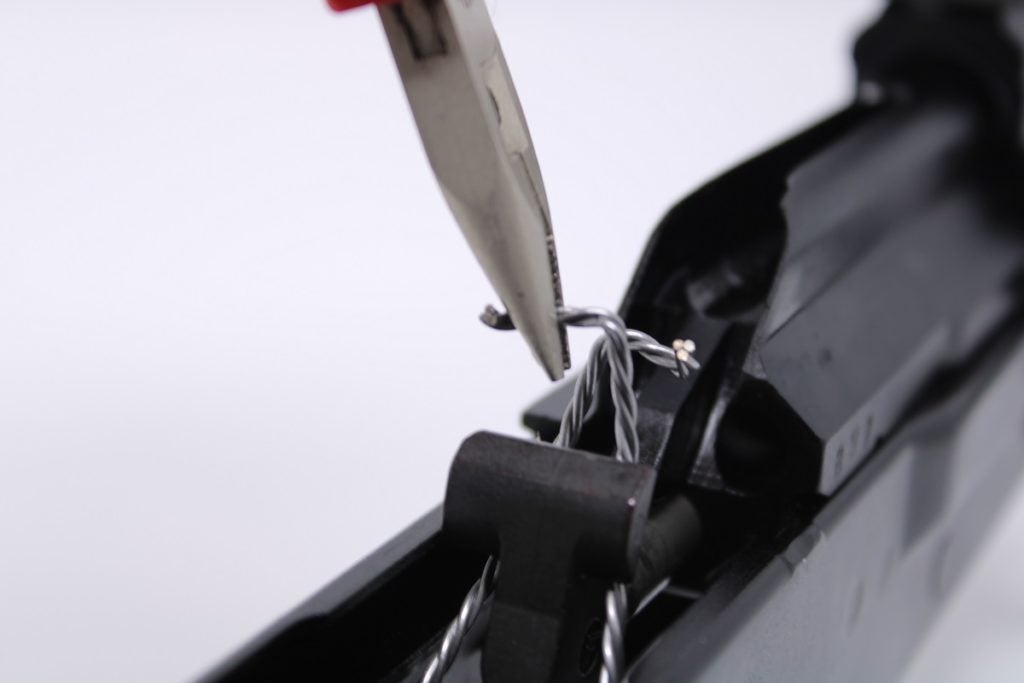
Repeat this with the opposite end of the main spring. Once both ends are at the hammer face, use steel wire or a bread bag twist tie to secure both ends of the spring.
If you do not tie up the spring ends, they will slip away from the hammer face when the hammer is removed from the receiver, striking the inside of the receiver. The spring ends are under high tension and have sharp edges; they are likely to cut you or cause injury if they’re allowed to slip.
Step 4: Remove Safety Lever
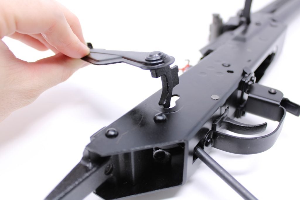
Rotate the safety lever up alongside the receiver so it is vertical, then grasp the lever and remove it from the receiver. It may be a tight fit and may require light tapping or wiggling to come loose.
Step 5: Remove Hammer & Trigger Pin Retainer Plate
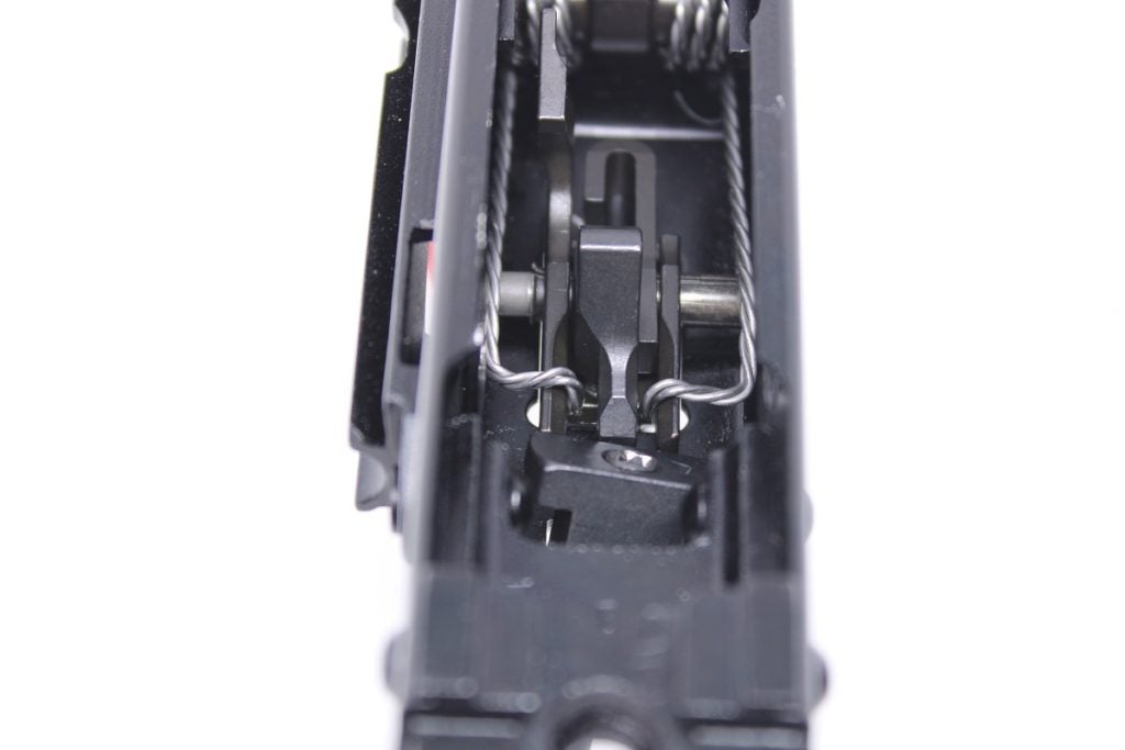
The pin-head end of the safety lever was keeping the hammer and trigger pins’ retainer plate seated. It can now be removed. As its name implies, this retainer plate captures the hammer and trigger pins, preventing them from becoming loose or walking out of the receiver.
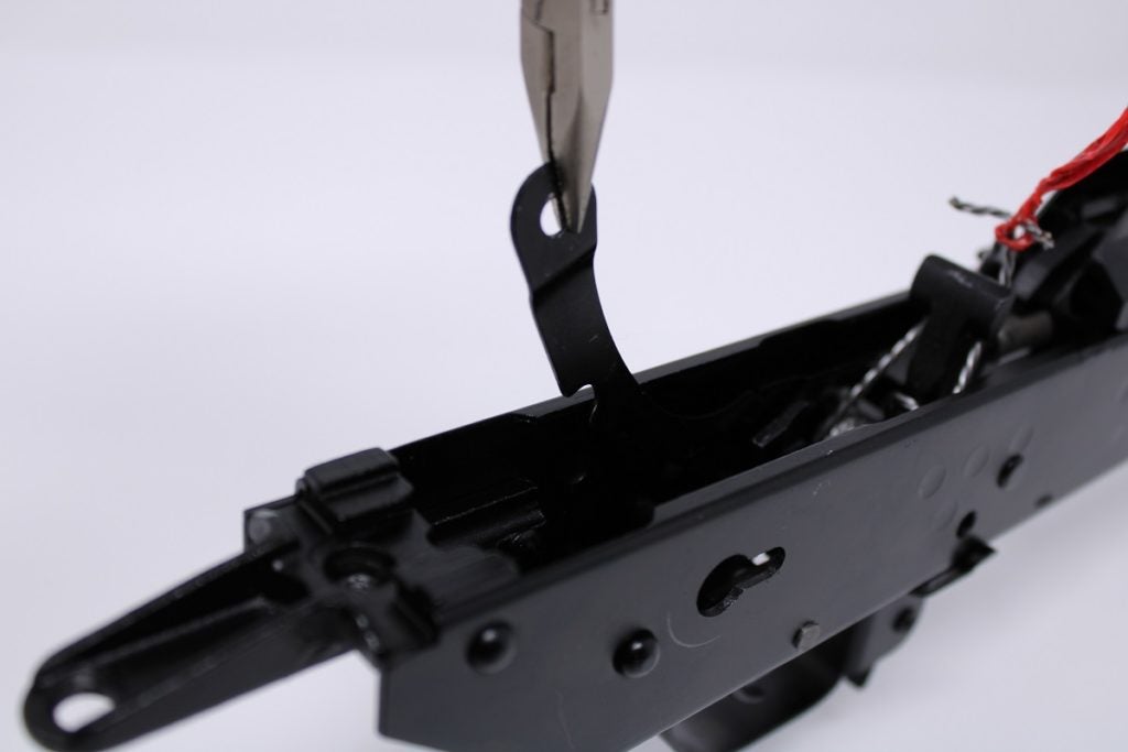
It must be rotated up and away from the trigger pin with pliers. It can then be gently pulled away from the hammer pin and removed from the receiver.
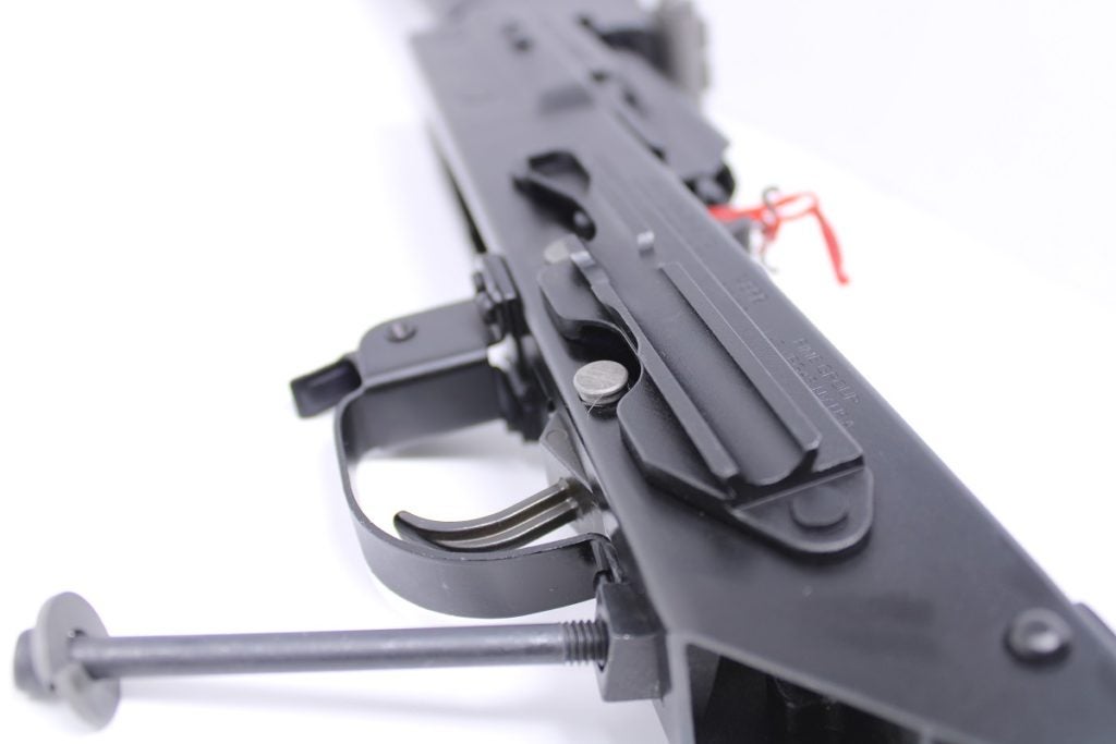
Step 6: Uninstall Trigger and Disconnector
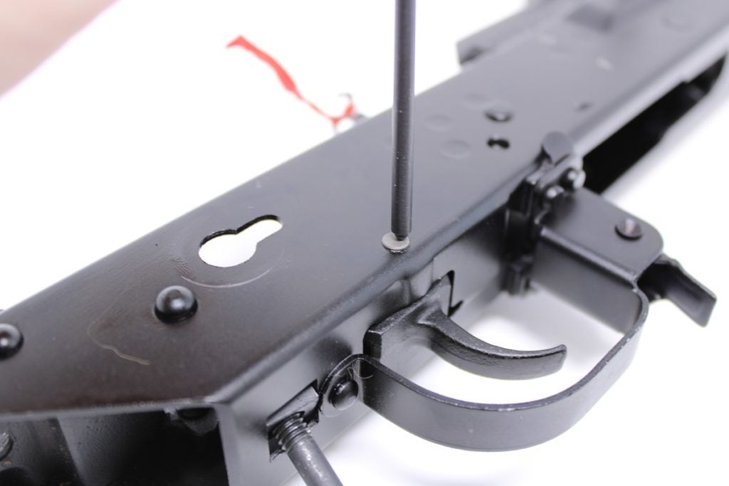
Using a small punch or screwdriver, lightly tap the end of the trigger pin from the right side of the receiver. On the opposite side, the pin should begin to fall from the receiver.
With the pin removed, the trigger and disconnector can be removed as one piece.
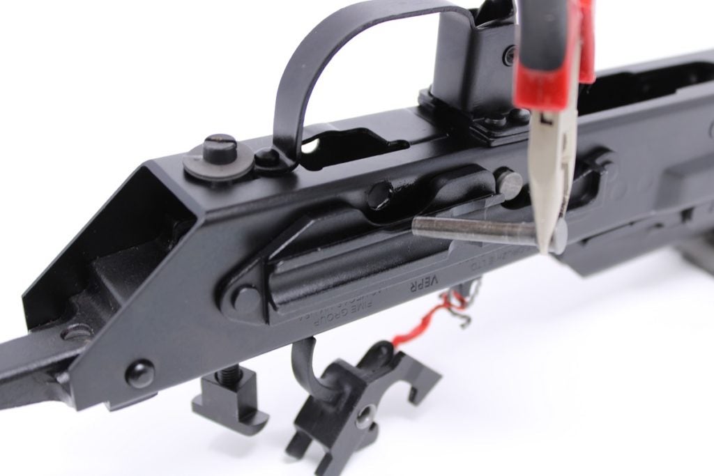
Step 7: Uninstall Hammer and Main Spring
Repeat the same removal process for the hammer: Tap the hammer pin from the receiver’s right side and pull it out from the left. Take care when removing the hammer and main spring assembly. Check the spring tie is not loose or slipping, or the spring could slip during removal and catch your hand or fingers.
Assembling the New Trigger, Disconnector, and Hammer
These instructions apply to the FIME trigger group designed for the Russian Molot VEPR. You may skip to step 8 if your trigger is a drop-in unit or came assembled. Your AK’s trigger may appear slightly different in appearance, or it may not come with a hammer retarder.
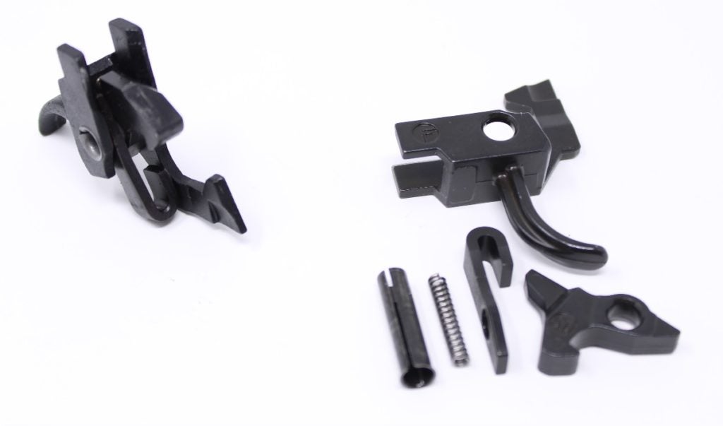
Use the factory trigger as a guide for assembly during these steps. First, rest the disconnector spring inside the disconnector:
Next, rest the disconnector inside the trigger with the disconnector hook facing the trigger hook. A small dimple inside the trigger should capture the end of the disconnector spring:
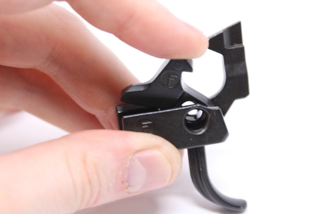
You must apply pressure to the top of the disconnector to align its pin hole with the pin holes in the trigger. It’s easiest to get the pin sleeve partially inserted into the disconnector and trigger before inserting the small hook-shaped hammer retarder.
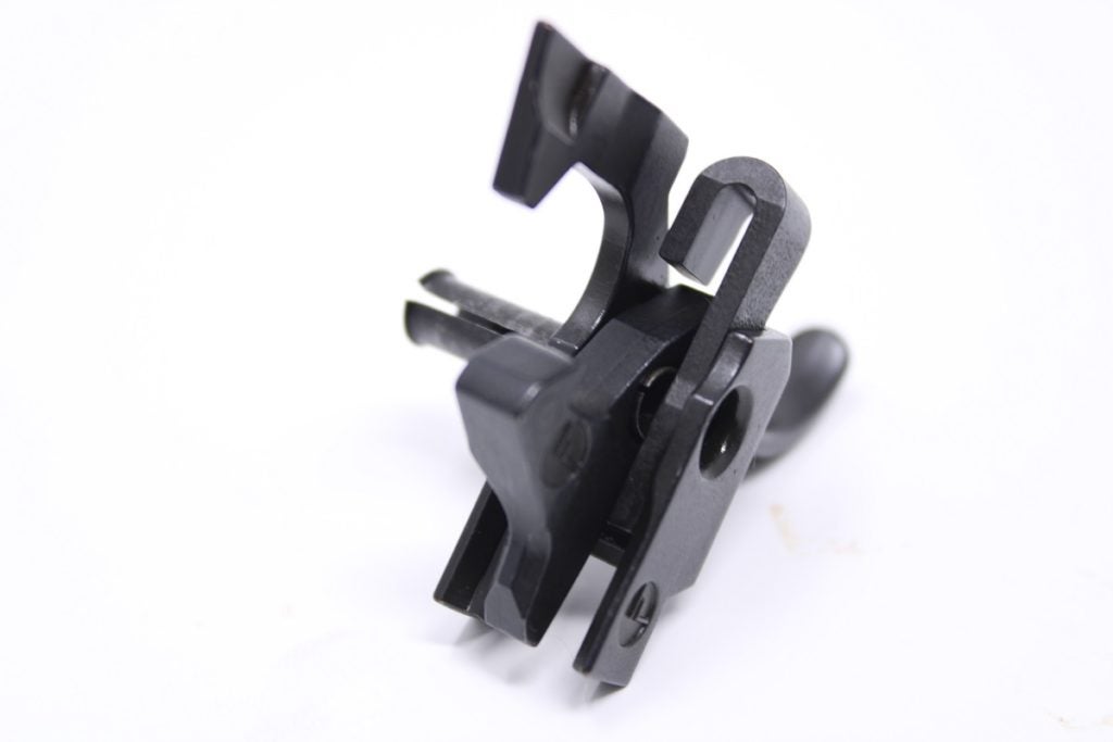
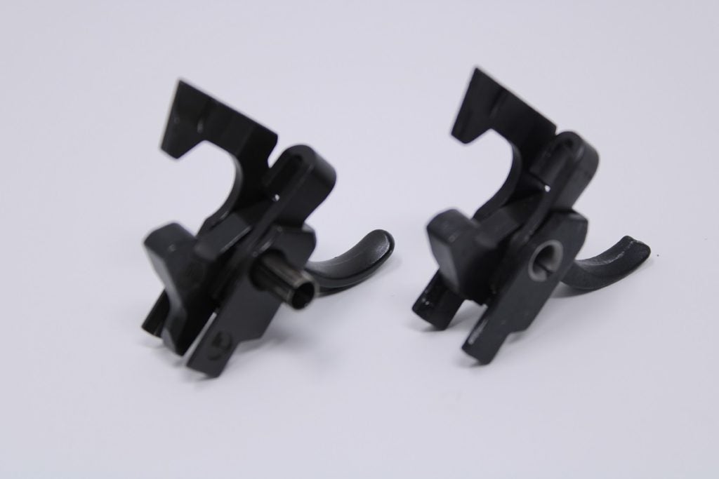
With the hammer retarder inserted and its pin hole aligned, continue pressing down on the disconnector to align it and the sleeve. Then press the sleeve through the trigger assembly fully. Once seated, a portion of the sleeve should protrude from the right side of the assembly. Compare your new trigger to the original to verify correct installation.
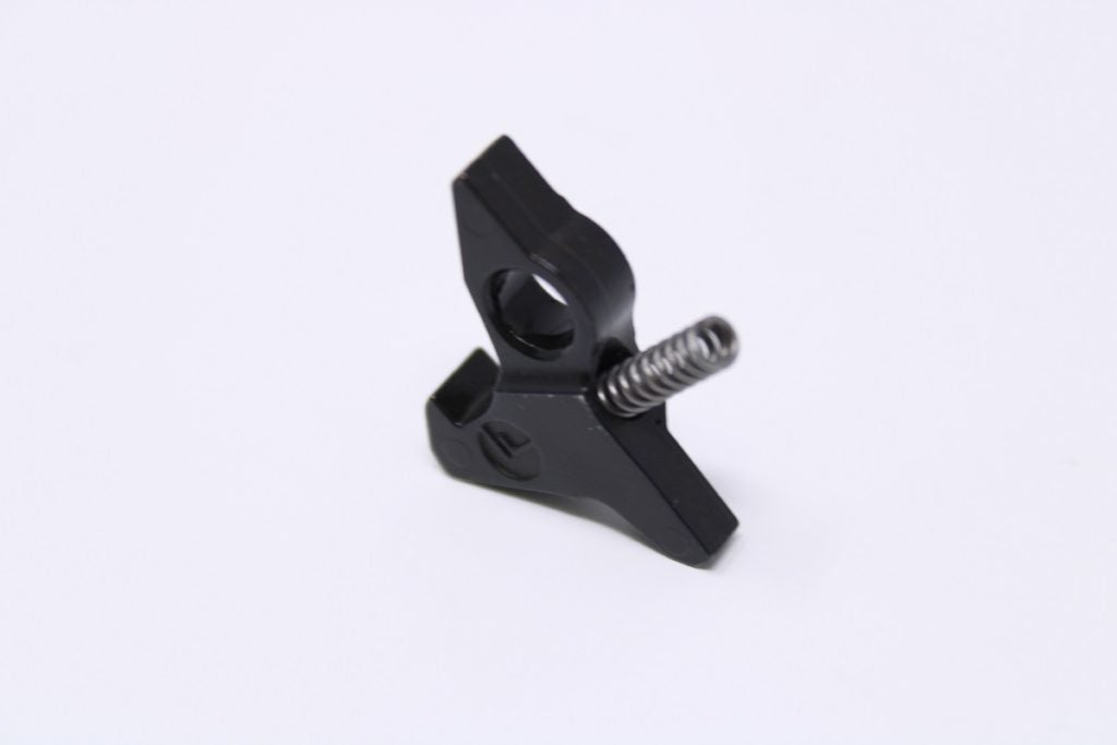
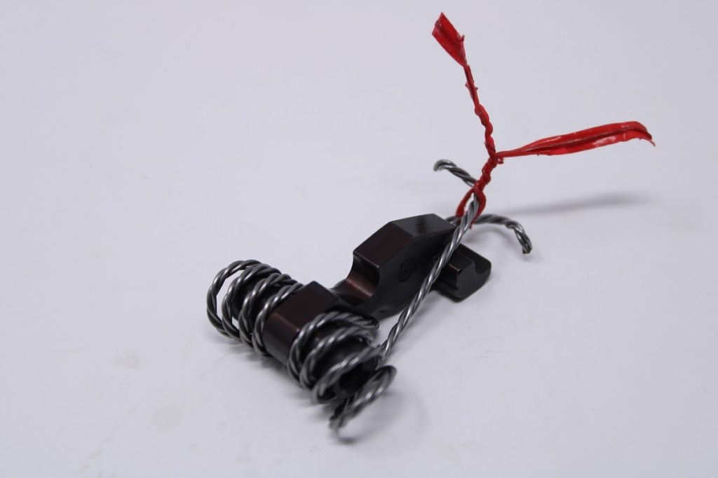
Lastly, the new hammer: First, carefully untie the main spring’s ends and allow them to fall away from the face of the factory hammer to remove tension. Be careful; they will want to snap back from the hammer. Next, pull on the loops of the main spring and remove the spring from the factory hammer. Orient the new hammer and spring as shown, and slide both loops of the spring onto the new hammer:
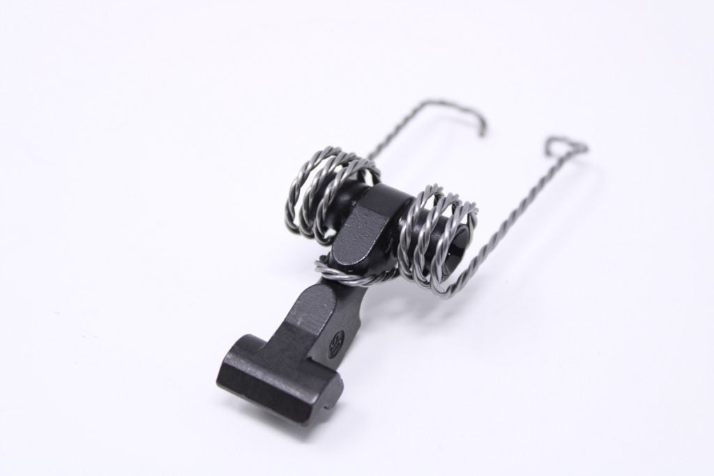
Ensure you have the same metal wire or twist tie you previously used to tie up the spring. Next, rotate the hammer upward and over, bringing it to rest between the main spring’s two ends. You will need to apply firm pressure to do this.
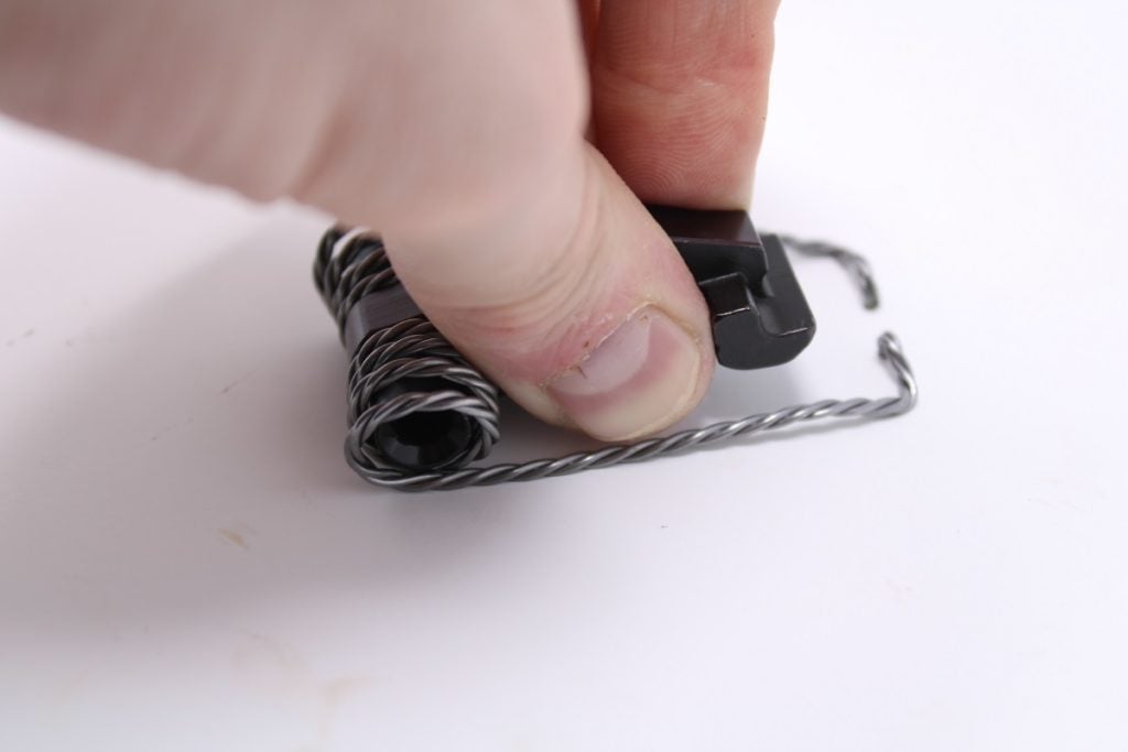
With the hammer pressed firmly flat, bring one end of the spring up and over top of the hammer face:
Repeat this step for the opposite end, then tie up both ends with your wire or twist tie.
Step 8: Install New Hammer w/ Spring
This is a reversal of step 7: Drop the hammer into the receiver and orient it so the strike face of the hammer is pointed toward the firing pin. Align the pin holes in the hammer and receiver, and press the hammer pin back into the receiver fully from the left side.
Step 9: Install New Trigger & Disconnector
Install the new trigger and disconnector. Ensure the trigger is centered in the receiver and the pin holes in the sleeve and receiver are aligned before reinserting the trigger pin.
Step 10: Reinstall Pin Retainer Plate
Ensure both the hammer and trigger pins are fully seated inside the receiver, otherwise, the retainer plate cannot be reinstalled. To successfully reinstall the plate, get the end of the plate fully seated so it captures the hammer pin, then rotate the plate downward so the second notch in the plate captures the trigger pin. Some force may be required to pop the plate onto each pin. Pliers are helpful for manipulating the plate. The loop on the left side of the main spring may interfere, too. A flathead screwdriver is helpful in nudging the spring loops away to make room for the plate.
Step 11: Untie and Re-Seat Main Spring
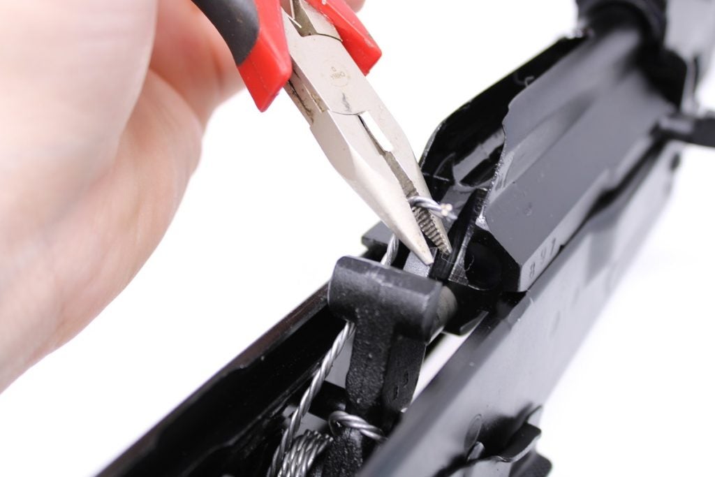
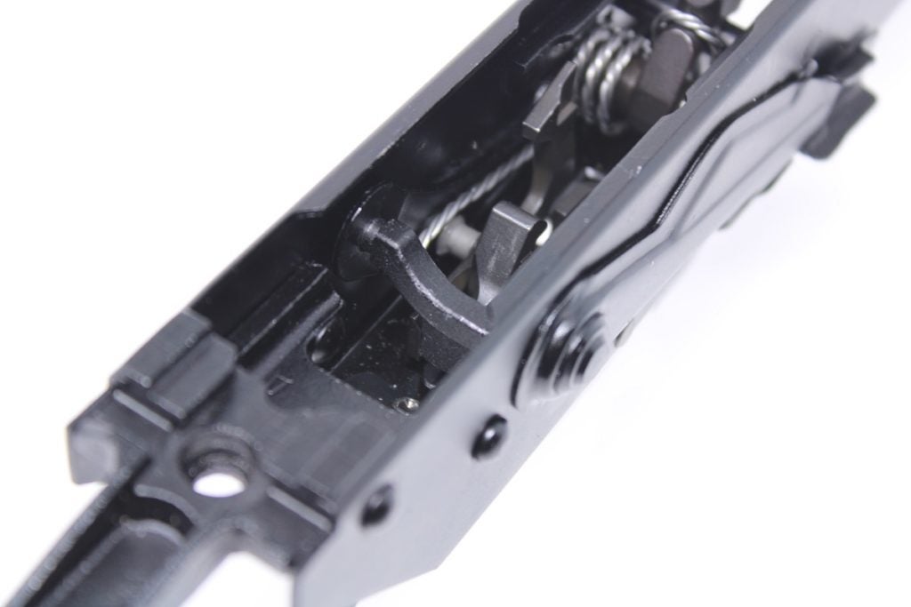
With the hammer, trigger, and retainer plate reinstalled, the main spring can be untied from the hammer. Using pliers, grasp each end of the spring and allow them to rest atop the trigger as shown:
Step 12: Reinstall Safety Lever
Reinstall the safety lever by orienting it vertically and sliding the pin end of the lever into the receiver. Ensure the pin on the end of the lever aligns with and is captured by the hole in the pin retainer plate. With the lever pressed flush against the receiver, rotate it downward into the “FIRE” position.
Test the Fire Control Group’s Function
Before reinstalling the guide rod and dust cover, confirm the functionality of the trigger, hammer, sear, disconnector, and safety. With the safety in the “FIRE” position, cock the hammer. Keep a finger lightly pressed against the hammer face once cocked. Pull the trigger to release the hammer. Allow the hammer to release but stop it from striking the firing pin to prevent damage to the pin. Re-cock the hammer while keeping the trigger depressed fully. The disconnector should capture the hammer and hold it down. Now, release the trigger. A small “pop” should indicate the disconnector handed off the hammer to the sear, with the trigger reset and the hammer cocked.
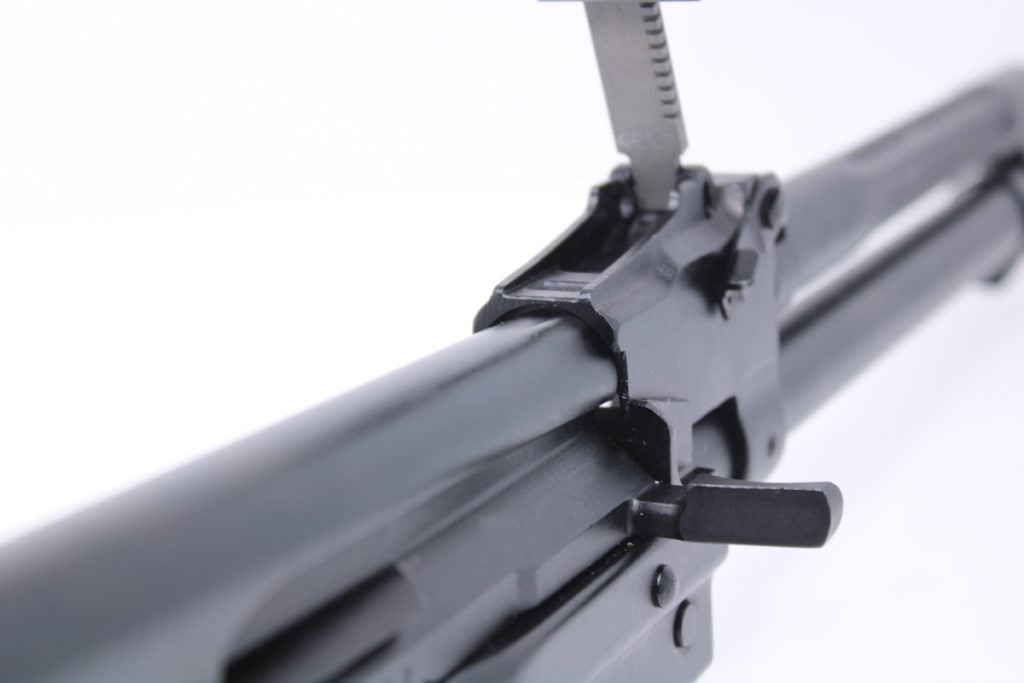
Step 13: Reinstall Guide Rod, Spring & Dust Cover
Insert the end of the guide rod into the bolt carrier and compress the rod and spring. Align the bottom end of the rod with its channel in the receiver so the receiver captures the guide rod as shown above. If your guide rod and spring are equipped with a protective plate, ensure that plate is resting over top the bolt carrier.
When reinstalling the dust cover, ensure it aligns with the small rounded channel located underneath the front sight base, behind the trunnion. Press firmly forward and down on the dust cover to force it over the rear of the guide rod’s button head.
Your Trigger and Hammer Install is Complete!
Your new trigger group is now ready for action. Before taking your AK to the range and test-firing, be sure to lubricate the hammer, trigger, disconnector, and pins. As with all new internal firearm components on any weapon platform, a break-in period may be required to get your new trigger and hammer running smoothly.
